So I’m nearly done. But of course not without some debugging😏. All the LEDs work and light uniform, cables are tested, faders and joystick work. But for some reason none of my buttons or switches work and the led of switch 5 is not lighting up eather. Any thoughts?

  • Jan replied to this.

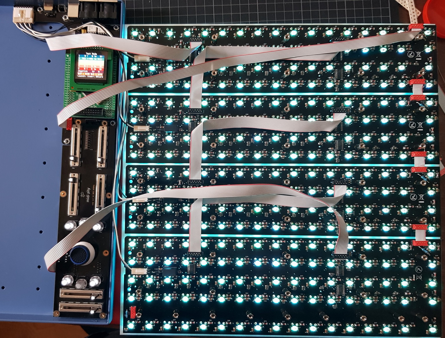
    For the Matias buttons, what happens if you connect firstly from the Core J89 to the second board etc.? How does it look if you disconnect the boards in turn, starting from neo_85?

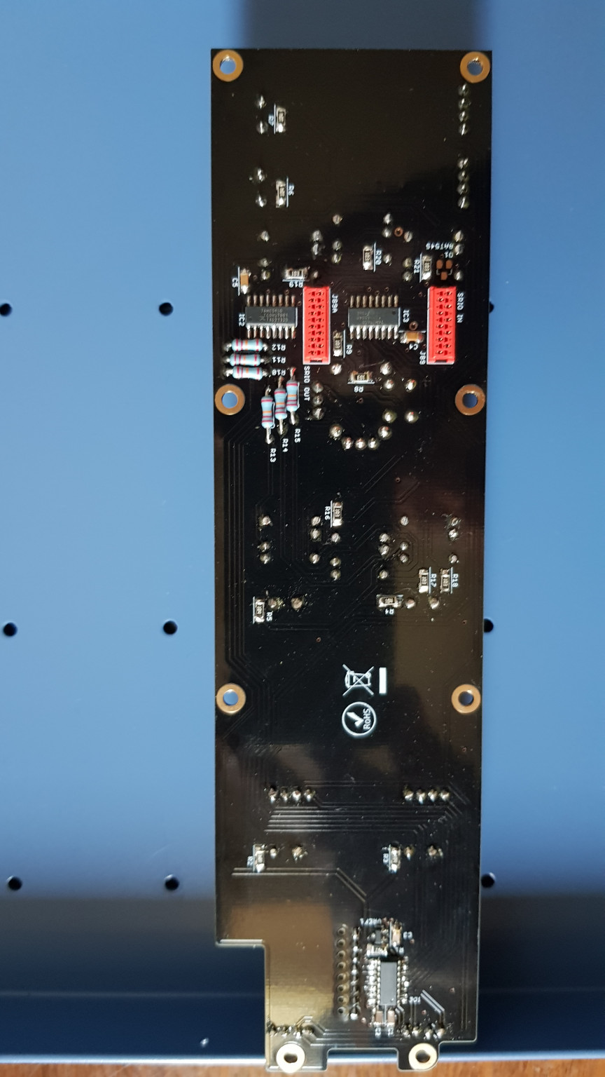
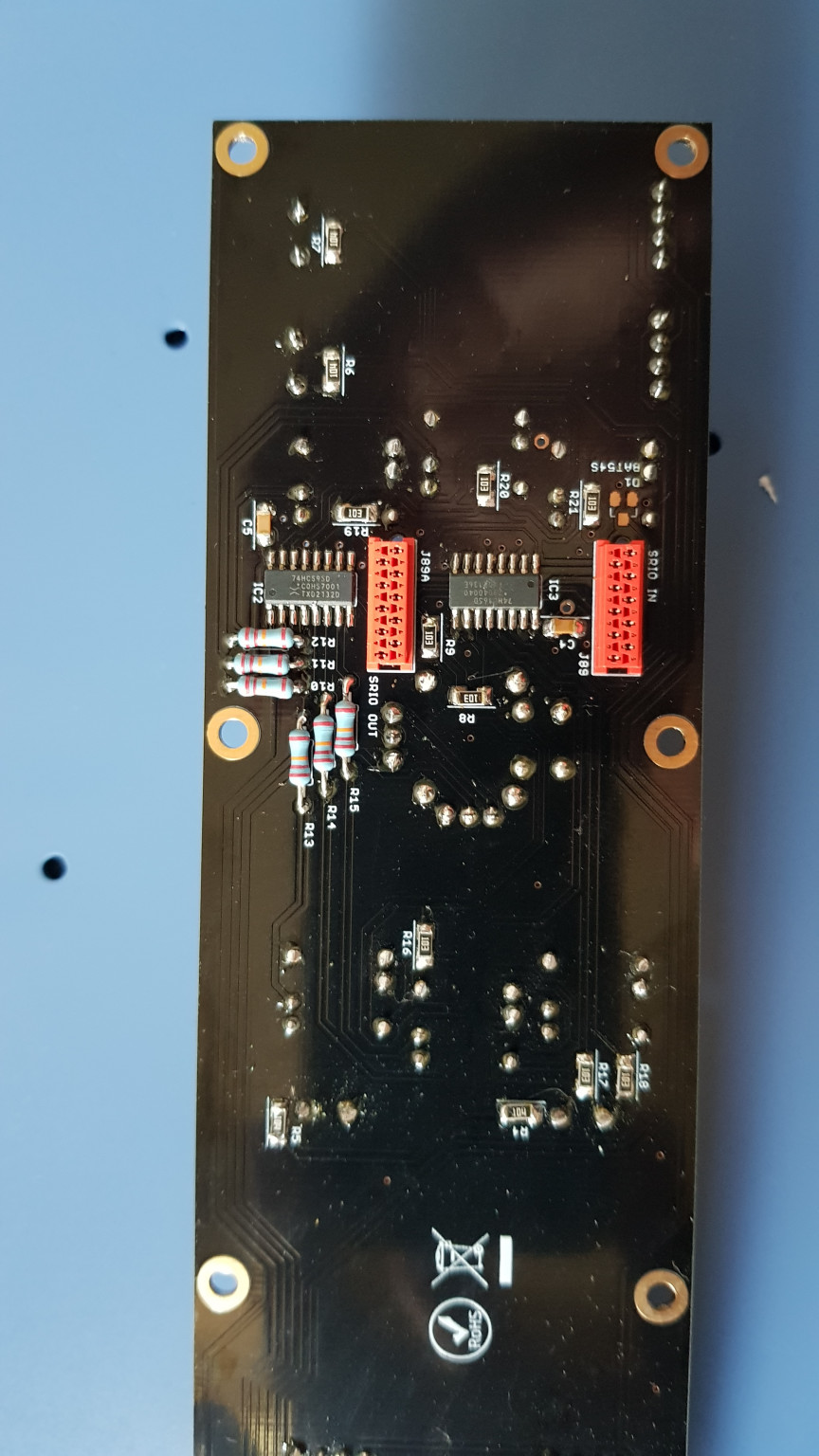
    Check the soldering around Core J89 and IC3. Maybe the data signals never leave/enter the board?

    How do the ICs look on neo_ boards? Any pins bridged? All diodes with the correct orientation?

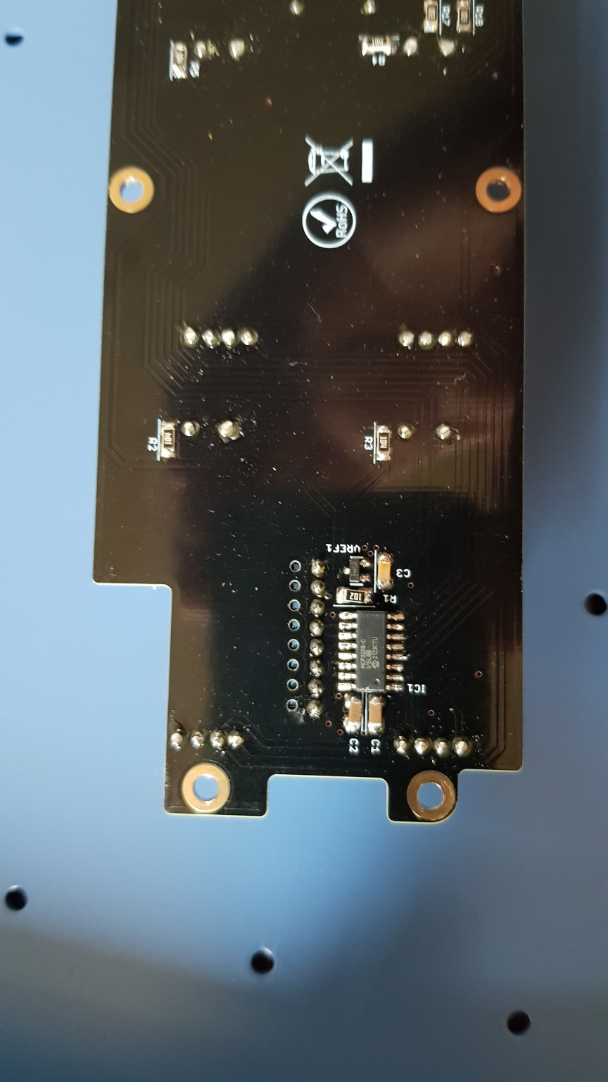
    Axes board IC1 could be nicer, but if it works probably leave it as is. For the LED, is it the proper bipolar type? Does it light up with a multimeter diode test? It should light up in two different colours depending on the orientation.

      Wait, don’t you have the cables backwards here? J89A is the output chain to the next neo_ board.

      • Jan replied to this.

        latigid on Indeed🤦‍♂️. I did made the same mistakewhen building the seq4. Thanks for pointing it out, since my soldering skills are more solid, I expect no further issues. The only things that worry me a bit, are that the new haven display is emitting a high pitched tone and that the ARM processor is getting very hot.

          Can be related to the quality of the PSU brick. You can remove the power and measure resistance from 0V to 3v3. The capacitors will charge up for a bit, but then the resistance should be quite high. If it is low, it could be to do with a short on the 3v3 rail, so check the pin headers, also maybe the ADC on the axes board.

            I’m using the Leicke PSU. So far everything seems to work, except for the axis switches.

              solved, another connection mistake. Lets blame it on the heath😊. I can start using it and will troubleshoot the new haven sound later. Thanks again for the support, Andy! much appreciated.

              Nice! Some have had luck with an additional capacitor (e.g. 100nF) across the 3v3/0V power rails, maybe directly on the OLED pins themselves. These two pins are on the left of the display header when viewed from the front.

              • Jan replied to this.

                Thanks! After testing I found 4 switches that need reflow and I wanted to clean the axis and core pcb anyways. I will try the display fix while I’m at it. See you in the serial number section later today! Ive had my eye on that 14 for some weeks already😄

                latigid on

                Write a Reply...