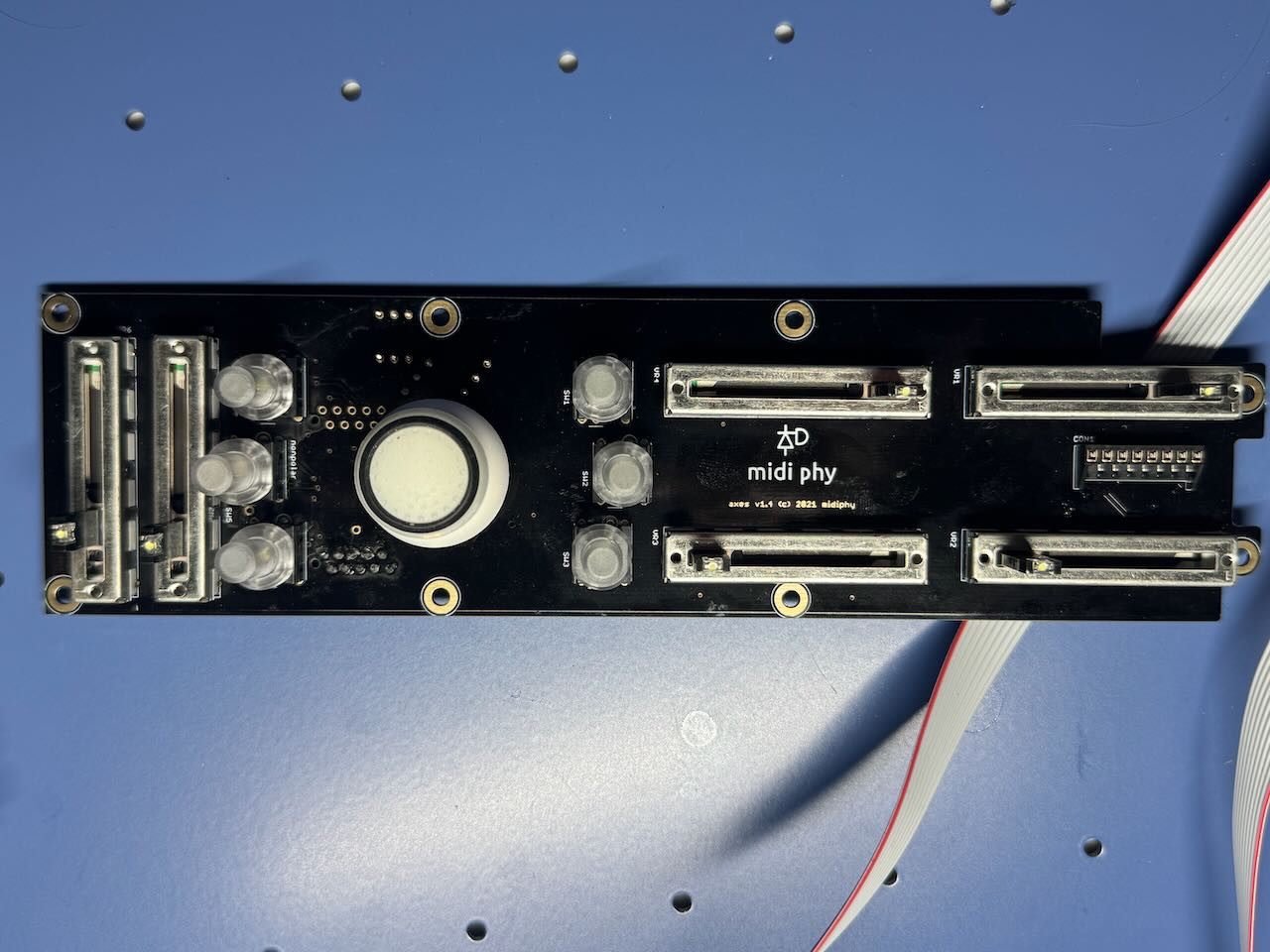
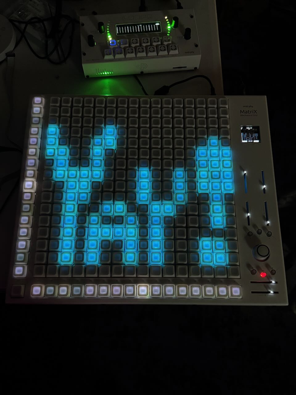
Tom9000 Sooooo…probably going to laugh at this one but it turns out I used the 14mm standoffs instead of the 10mm and CON1 was not making contact after all. I found the correct ones, switched them out and all the sliders and joystick work great. I hooked it up to the switches/led boards and it’s very cool how you have the sliders and joystick visualized in the Matias switches!
That’s a new one I think! Glad that it works, but I really wonder about the sparks from before…!
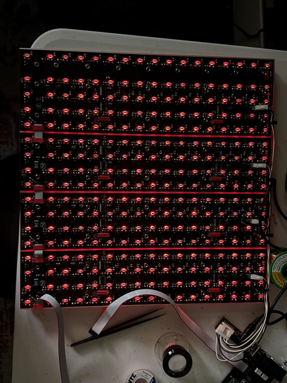
The six buttons do not trigger anything though, except the switch BLM ports which changes from green to red and there is a fast popup message in the OLED. The other 5 buttons do not light up or register. Attached are pics of the board but I feel like I’m pretty close here!
That is a good sign, if that LED changes colour when pressed it suggests that the digital signals are being read back through the board, and that the 74HC595 chip is the right way around. I’m not sure what the other MEC switches should do; maybe this is the time to connect to the LoopA and give it a spin?
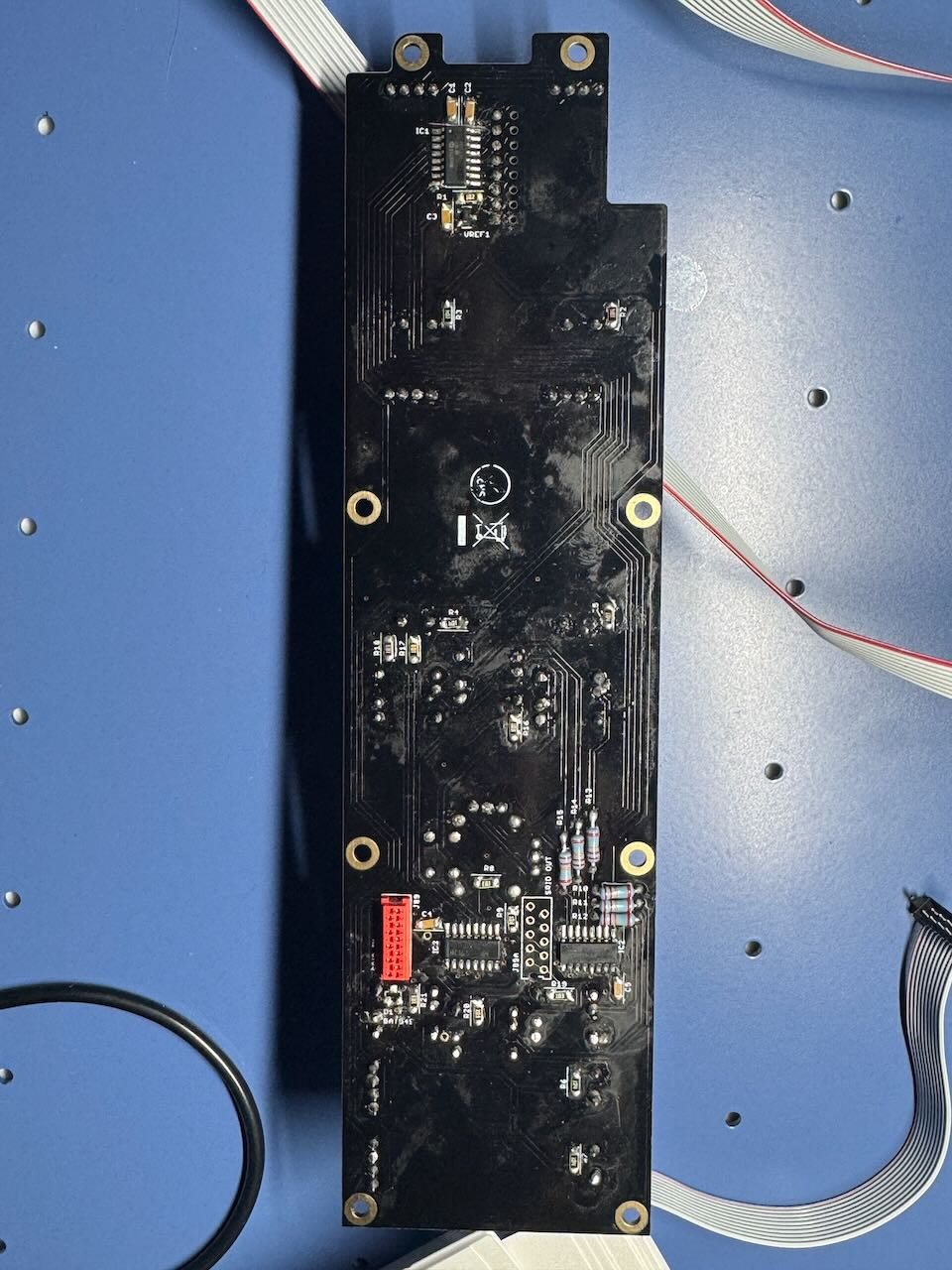
If the LEDs on the MEC switches don’t light up when pressed, then it could be that the LEDs are inserted around the wrong way. On bottom side of the PCB, the encircled pin is the anode and the flat marking indicates the cathode. Don’t PANIC (Positive Anode, Negative Is Cathode). With your multimeter in diode mode, which way around do the probes have to be to light up your LED?