Good day,

currently I’m testing the JA PCB. Here I’m encountering a small issue: SW14 (leftmost in the lowest row) does not work. I tried to resolder all the point of the switch, no luck.. Do you maybe have an idea what the issue could be? All other switches are working fine.
Thanks!

    Hello,

    Doesn’t work as in… no DIN event in MIOS Studio? No LED? If you upload a photo I could try to check the soldering work, but as other switches in the matrix are functional it would appear to be isolated here.

    Apart from the switch not being soldered in properly (cold joints), the most obvious issue is that the 4148 diode is backwards or faulty. Sometimes these boards go funny if there are LEDs installed with incorrect polarity or even broken LEDs.

    You can also try to manually connect the matrix but how you would bodge it depends on what part is non-functional.

    LED anodes connect across a row, so you could connect to the next switch pin with the circle.
    4148 anodes connect across a row, D14 cathode to bottom-left pin of SW14 when viewed from the front.
    “Switch cathode” connects to SW9 above; for simplicity’s sake that is the LED pin marked with a dash.

    • Eggi replied to this.

      latigid on Hi Andy! Thank you for the quick reply.
      Not working as in no DIN event in MIOS studio and no LED. I tried to resolder the points of the switch, but that didnt help sadly . The 4148 diode is also not backwards, maybe i got a bad one or damaged it by accident? The LED polarity should be fine i double checked all the LEDs beforehand. Here, some pictures of the soldering:

      • Eggi replied to this.

        Eggi Tried another diode, still not working. The lower left gold ring of SW8 fell off of my PCB, could that be related?

          Hi, yep, a broken pad will cause issues!

          Please see a layout viewed from the front of the board. I would suggest to bodge the diode directly to the lower-left pin as indicated with the yellow line. The lower-right pin is also an option if things are too scratched up (the silkscreen marking indicates that the pins are internally connected within the switch).

          You can also see the connection highlighted in red to SW9 to bridge if you need to connect the common cathode line of the matrix.

          • Eggi replied to this.

            Hi,
            another small issue: I’m currently testing the LeMEC boards. SW9-12 (lower left Matias) on the RH PCB doesnt show any signal in MIOS Studio, when contacting with a piece of metal. All other switches and encoders on the LeMEC boards are working fine. I found this thread with a similar issue, seems like reflowing a few points helped there, no luck so far for me. The diodes are all in the right polarity. Could this also be related to the broken pad on the JA PCB? Some pictures attached:


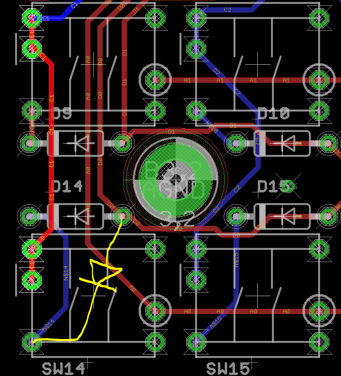
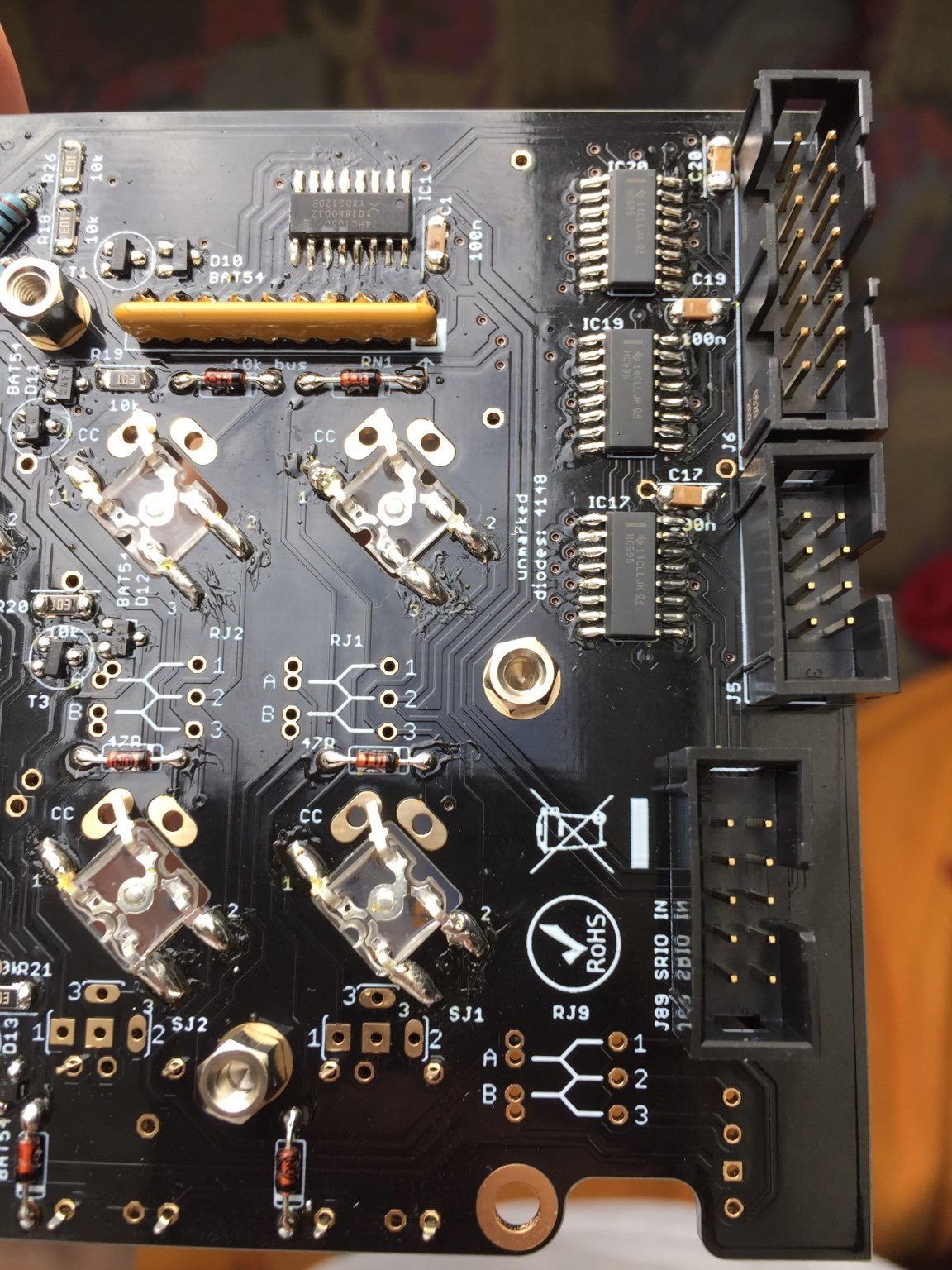
              I don’t think it would be related to the broken plated hole on JA.

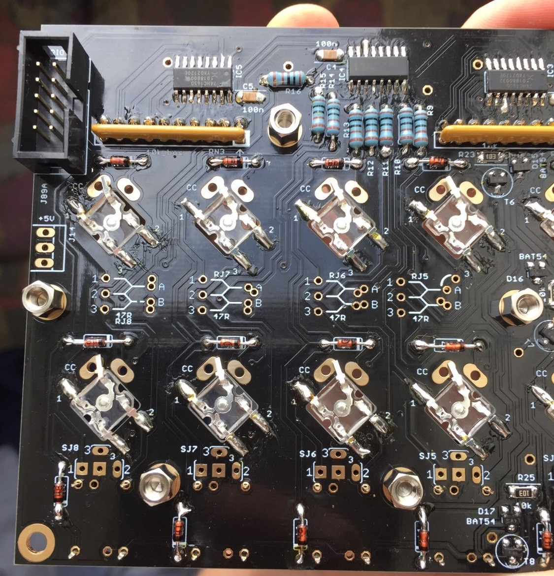
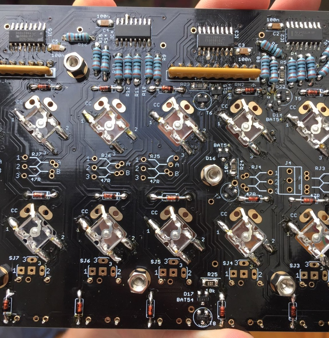
              Many of the joints look like they aren’t formed properly, e.g. R15, IC3 pins 16, 15, 11 etc. amongst others. If you have a ball like that, it can be that there is insufficient contact to the pad below. In this case, retouch and if necessary add a bit of flux to get things to flow properly and make “volcano-like” joints. You might need to increase the soldering iron temperature.

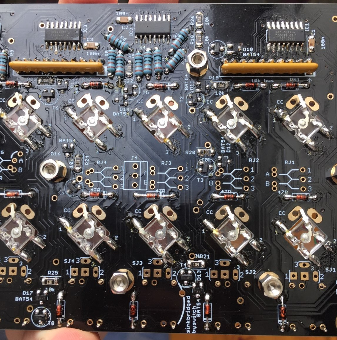
              If it is four switches not working and the switches in same columns do work, it points to the sink driver. That is:
              T3
              D12
              R20
              R3
              IC2, pin 5

              Looking at the pictures, it seems as if those joints on those could be touched up better.

              • Eggi replied to this.

                latigid on Thanks again for the quick reply!
                I think I might have overdone it a bit with the tin, many of the balls are there because I added even more when trying to resolder some points..
                I tried to correct the parts you mentioned, sadly no luck yet. Also gave all the 4148 diodes another go, no change.. One strange thing I noticed: one of my PCs is unable to connect to the midibox now, worked fine earlier… I always get the message: “No response From mios8 or mios32 core”. On my laptop it’s still working fine. Maybe thats a sign I should go to bed for today.. 😅 I’ll try some more resoldering tomorrow and will report back, if I get it to run. Thanks again!

                  When disconnecting the USB power, always close and restart MIOS Studio again. Failure to connect could indicate that the USB power supply from the PC is noisy or doesn’t supply sufficient current to drive the SEQ properly.

                  New day, new luck, fingers crossed!

                    Did a small nightshift since I couldn’t get it out of my head haha. Still no progress. Is there any other specific part aside from the ones listed above that I could check in relation to those four switches? I think I gave all the parts aside from the ICs another go (tried IC2 twice, first I think it looked a bit better, now I think its even worse, pin 5 should be good tho, neither try did work). Is one of the other ICs related too? Since soldering didnt work out, I’ll give that sleeping idea another try. Good night 😀

                      I know the feeling 😀
                      As I mentioned, the two “sides” of the switch matrix will tell you what’s wrong. If the switches in same columns do work, it points to the sink driver. You should be able to trace continuity from the IC pin through the resistor R3 to the transistor base (closest to R20). You could check that the transistor and BAT54 diode have the correct markings in case they were inadvertently swapped, also that there are no shorts between any of the pads of individual components.

                      It is possible that one or more components were damaged by overheating or static discharge or were simply DOA.

                        After some more soldering SW 17-20 stopped working too and one of the pads of D10 came off. I’ll try my luck with a new board.

                          6 days later

                          Good day,
                          After a long night of soldering on friday, I finished the box!
                          Had two cases where the superflux LEDs did not want to light up in red on the RH LeMEC - SW15+16: 15 could be fixed by reflowing some of the RJ resistors I think; 16 had to be replaced.
                          One small issue left: the color mixing of the superfluxes on the right LeMEC board doesnt look as nice as on the left side. Both red and green individually look fine, but mixed it looks light green instead of orange. All switches of the RH LeMEC are affected. Would you maybe have another tip for me on what I could check here?
                          Thank you!

                            Hi!

                            Well done first off!

                            We have found that the red dies (LED elements) can be a bit more sensitive (to heat I think). But this is a good reason to have a few spares on hand.

                            Regarding variable brightness, assuming the RJ values were all correct, the brightness is practically controlled by the on/off time of the matrix, so each LED “row” will be on 1/8th of the time. What could affect this is capacitive effects e.g. from flux residues. You might try cleaning the board especially around the 595 ICs and associated resistors. Could also be how the LEDs were soldered in?

                            Also check the +5V voltage on the board, e.g. across any 100nF capacitor. See if there is a big difference between the two lemec boards? That could also indicate not exactly a short circuit but some leakage. Hard to say!

                              7 days later

                              Hi,
                              thanks again for the tips!
                              I’ll try when I have some time during the next weekends.
                              Would you maybe have a PO box or an address, where I can send you some beers as thanks? I’d also have quite a lot of 26-pin flat ribbon cable left (100FT+), if you have a use for that. It would just gather dust at my place.

                              Hi,

                              Thanks for the offer! No need for ribbon cable; I think I’ve got a similar reel here that I break apart into smaller widths 🙂
                              .
                              If you would like to donate for the support, here’s a link . Really hope you can get it working right!

                                7 months later

                                I just completed my core build. I was trying to update the bootloader firmware on my core, but the USB B port would only light up the power light on the wave core. I managed to upload the bootloader via the core usb port, but now my USB B port doesn’t provide power to the wave core board. There is resistance between the USB power and PA11 and PA 12 on the wave core when measured at 200 Ohm with a multimeter . I’m worried I fried something.

                                  Please check the settings of the SEQ’s USB/OTG switch and the switches on the waveshare board, also restart MIOS Studio after each Core reset. It is also possible to try the upload over mini USB, but you have to switch the settings back after.

                                  Other common culprits are MacOS USB MIDI drivers and poor cabling between the USB breakout and the Core PCB.